Understanding 3-Phase Motor Wiring
- David Peterson

- Jul 13, 2020
- 4 min read
3-phase synchronous motors are just about the simplest of all motors that can be created. The simplicity is due almost entirely to how 3-phase electricity works.
Alternating Current (AC) electricity switches directions 60 times per second, which means current flows through the wires one way, then the other, and repeats 60 times every second.
This current in the wires creates an electromagnet, forcing the internal rotor in a circular motion.
Each of the three phases has 2 coils on opposing sides of the motor. This creates a well-balanced push and pull applied to both sides of the motor equally at any given time.

A normal 3-ph synchronous motor has 6 separate bundled coils of wire around the outside of the housing.
In a 3-phase motor, the direction of rotation is quite predictable. If the phases are energized in order of Red, Blue, then Green, we could observe that the motor should rotate Clockwise according to the picture.
However, if you were to energize the coils in any other order, perhaps Blue, then Red, then Green, the direction would be reversed. The classic method of reversing a 3-phase motor is by reversing any two of the supply wires.
Wiring
Most 3-phase motors can be wired to work in either a high or a low-voltage circuit. Low voltage is along the lines of 208-240 volts, but a high voltage would be on the order of 277-480 volts.
There are two main wiring schemes in a typical 3-phase motor.
Wye-Wound
The technician can see both ends of 3 of the coils, and one end of the other 3. The remaining 3 ends are connected together inside the motor.
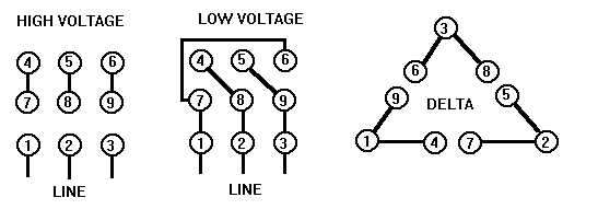
In the diagrams below, the coils are represented with bold lines between terminal numbers on the far right side. The motor will have a junction box on the side with 9 numbered (often colored) wires, and a diagram that looks similar to this on the data plate.


For High Voltage, terminals 4-7, 5-8, and 6-9 are joined together creating one large Y-shape. When the supply voltage is applied to terminals 1, 2, and 3, the current must travel through 4 coils no matter which terminals it travels between.
In the terminology of a normal circuit schematic, the high-voltage winding places 4 coils in series between any two input terminals. This means that the resistance should measure 4x that of a single coil.
For Low Voltage, one end of the 3 isolated coils are bonded together with terminals

4-5-6. This creates two side-by-side smaller Y-shapes. The supply voltage must then be sent to both of the smaller Y-shapes at one time. This means that there are only 2 coils in between each supply terminal, but there are two side-by-side paths. Although it is only half the voltage, the two parallel coils will use twice the current. If the voltage is half, but the current is double, the total Horsepower of the motor is the EXACT same, no matter which wiring voltage is used!
The low-voltage winding places 2 coils in series, but 2 of these series in parallel with each other between input terminals. Therefore, the resistance should only measure 1x that of a single coil.
Delta-Wound
A similar set of connections will allow a Delta Wound motor to be wired by the technician. These are fundamentally different from the Wye wound motors before, since all 6 coils allow connections at both ends. However, every set of 2 coils has one end bonded together inside the motor. This is in contrast to the internal Y shape that consumes one end of 3 coils internally. However, the terms of series and parallel still apply.

For High Voltage, the connections again place the outside coils in series with each

other by joining 9-6, 8-5, and 7-4. However this time, there are two alternate paths for current between any two supply terminals. One path leads through two series coils, the other path through 4 series terminals. Picture the supply connections 1 and 3. Directly between these terminals are the two coils joined at 9-6. Additionally, the current can travel through 4 coils from the 7-4 junction to terminal 2, then to the 8-5 junction, and finally to terminal 3.
A resistance measurement in this case would lead to a parallel circuit of 2x coils and 4x coils in series, respectively. A combination circuit simplification leads to a measurement of 1.33x the resistance of a single coil.
For Low Voltage, the supply lines are connected to one point on each of the three delta connections. This is a fairly simple circuit that places three parallel coils together between any two terminals.

Although the circuit is simple, you must be very careful to connect the CORRECT three terminals to each of the supply lines. For example, the diagram lists connecting 1-7-6 to a supply line. If you instead connected 1-7-8 to a supply line, the current would still have the same amount of resistance from line-to-line. However, one of those coils would now be incorrectly magnetized and would oppose the rotation of the motor. The diagram must be strictly followed.
For this measurement between any two supply terminals, we would expect a value of 0.33x the resistance of a single coil.
Summary
3-Phase motors are very simple in construction, but genius in operation. They are certainly worth understanding due to their common appearance in nearly every facet of industry - from manufacturing to HVAC and many conveyor and material handling systems.
To learn more about motor operation and the VFD units that control them, check out our training programs and products designed for classrooms and industry!


Comments